Pedal-Assist E-Bike PI Controller
PI controller for pedal-assist e-bike application with real-time hardware implementation
Overview
Designed and implemented a velocity control system for a DC motor using PI control, applied to a pedal-assist e-bike scenario. The system maintains consistent wheel speed through feedback control with zero steady-state error.
Highlights
- PI controller achieving zero steady-state error and <10% overshoot
- Real-time implementation on Arduino Mega 2560 with DC motor hardware
- MATLAB/Simulink design verification matching hardware performance within 5%
- Root locus analysis for stability verification and pole placement design
- Square-wave tracking with 0.35s peak time and disturbance rejection
Tech Stack
Problem Statement
The goal was to design a pedal-assist electric bike controller where the rider's input pedal torque is scaled by the motor for easier riding. The motor scales torque to a user-selected assist level (Eco/Normal/Sport), and the controller maintains the assisted forward velocity even when terrain or load changes. The system must measure rider pedal torque, scale it according to assist level, convert the scaled signal into a desired velocity command, and use velocity feedback from the motor encoder to track the desired velocity with good transient response and zero steady-state error.
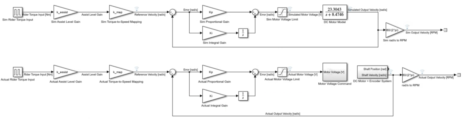
Block diagram of pedal-assist e-bike control system showing torque sensing, assist level scaling, and velocity feedback loop
Control System Design
- Selected PI controller structure: C(s) = Kp + Ki/s to achieve Type 1 system for zero steady-state error
- DC motor plant model: G(s) = 23.3043/(s + 8.4746) from prior system identification
- Designed for ζ = 0.8 damping ratio and ωn = 9 rad/s natural frequency to meet overshoot and settling time specs
- Calculated controller gains: Kp = 0.254 and Ki = 3.476 using pole placement equations
- Closed-loop poles at s = -7.2 ± j5.4 confirming stable second-order response
Implementation Details
Implemented on Arduino Mega 2560 with fixed-step Euler integration (0.01s sample time). The reference velocity is generated from simulated rider torque via pulse generator: ωref(t) = kmap × kassist × τrider(t). The controller computes motor voltage command with 12V saturation limit. Encoder feedback provides actual velocity in RPM for closed-loop control. Hardware parameters matched simulation using Fixed-step ode1 solver in Simulink for accurate real-time performance prediction.
Design Specifications Met
- Zero steady-state error: Confirmed in both simulation (0%) and hardware (0%)
- Percent overshoot: 3-4% actual vs 2-3% theoretical (well below 10% limit)
- Peak time: 0.35s matching simulation, within 0.2-0.5s rise time specification
- Settling time: <2.0s requirement met with fast convergence to reference
- Velocity range: 0-250 RPM operating range maintained with stable performance
- Disturbance rejection: Controller maintained velocity during applied load disturbances
Root Locus Analysis
Performed root locus analysis on open-loop transfer function L(s) = K × bm(Kps + Ki) / [s(s + am)]. System has poles at s = 0 and s = -8.4746, with zero at s = -Ki/Kp ≈ -13.67. For K = 1 design gain, closed-loop poles at s = -7.2 ± j5.4 place the system in stable left-half plane with appropriate damping. One root locus branch terminates at the zero (-13.67), while the other extends to negative infinity on the real axis. This confirms the PI controller maintains stability across the operating range.
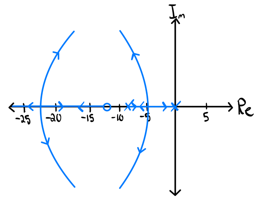
Root locus plot showing closed-loop pole locations and system stability with PI controller gain variation
Simulation Results
MATLAB/Simulink simulation of the PI controller with the DC motor plant model demonstrates the system's response to a square-wave reference input. The velocity output (blue) closely tracks the reference signal (red) with minimal overshoot and fast settling time. The controller achieves zero steady-state error, confirming the Type 1 system design. Peak velocity reaches approximately 204 RPM with 0.35s peak time. The motor voltage command (not shown) saturates at 12V during transient response, then settles to the steady-state value required to maintain target velocity.
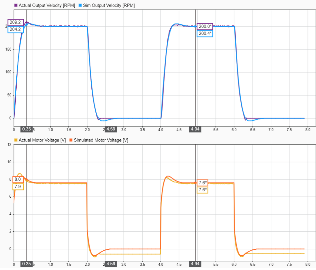
Figure 1: Simulink simulation showing velocity reference tracking with PI controller
Hardware Implementation Results
Real-time hardware testing on the Arduino Mega 2560 with DC motor showed excellent agreement with simulation predictions. Peak velocity measured 209.2 RPM (vs 204.2 RPM simulated), motor voltage peaked at 8.7V (vs 8.4V simulated), and peak time matched at 0.35s. Hardware exhibited slightly more overshoot (3-4%) and measurement noise due to physical motor dynamics, encoder quantization, and electromagnetic interference, but remained well within the <10% overshoot specification. Square-wave reference tracking demonstrated fast response with zero steady-state error. Disturbance rejection testing with applied mechanical load confirmed the controller maintains target velocity through simulated terrain changes, validating the pedal-assist e-bike application.
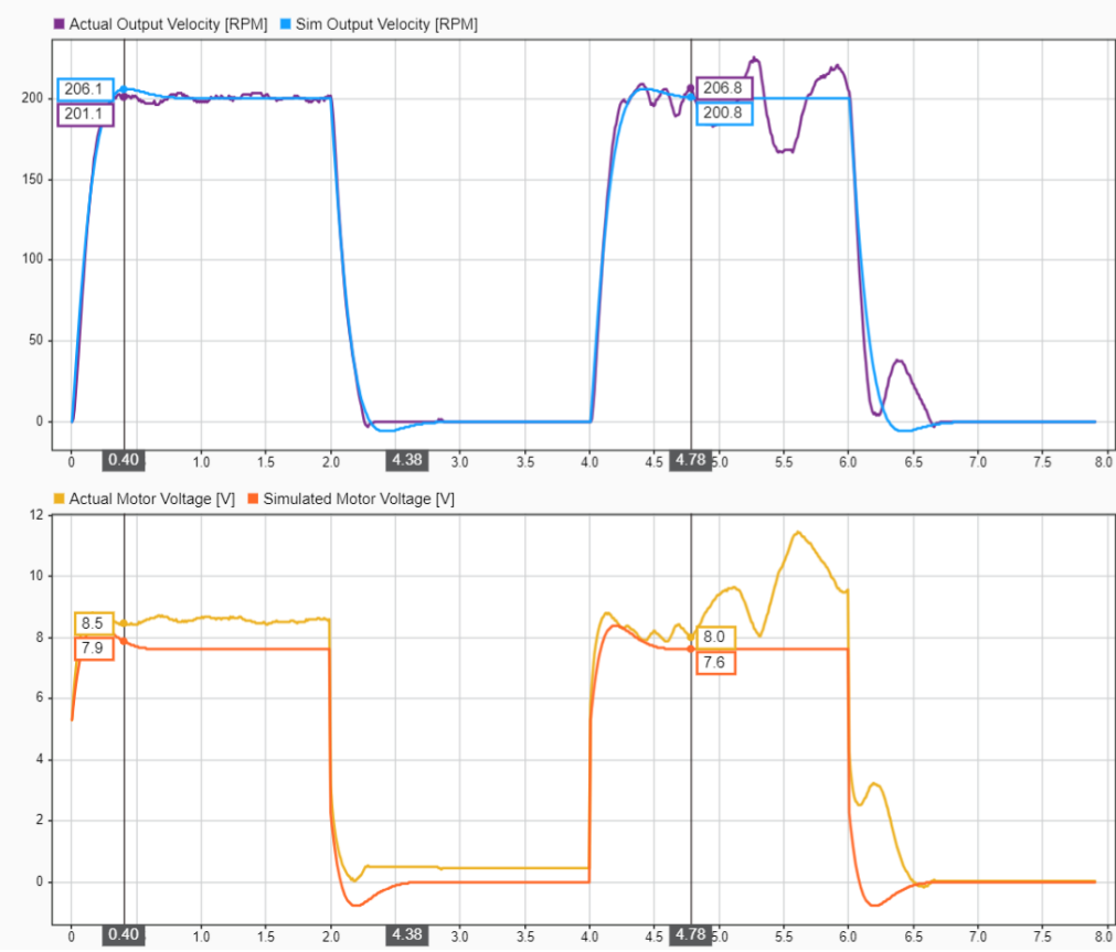
Figure 2: Hardware test results showing velocity tracking and motor voltage response on Arduino Mega 2560
Key Learnings
- PI control effectively eliminates steady-state error in velocity tracking applications
- Damping ratio selection (ζ = 0.8) critical for balancing fast response with minimal overshoot
- Simulation with accurate plant model provides reliable prediction of hardware performance
- Root locus analysis validates stability and pole placement before hardware implementation
- Real-world hardware shows noise and nonlinearities not captured in linear models, requiring tuning margin