SpinTrack
Real-time cycling performance computer with STM32, FreeRTOS, and TouchGFX UI
Overview
A real-time cycling performance computer providing cyclists with live data including speed, distance, heart rate, temperature, and elapsed time. Built on STM32 with FreeRTOS task scheduling and TouchGFX interface.
Highlights
- TouchGFX graphical UI with real-time speed, distance, heart rate, and temperature display
- FreeRTOS task architecture for concurrent sensor polling, timing, and UI updates
- Hall-effect wheel sensor with ADC for accurate speed and distance measurement
- AD8232 analog front-end with custom contact plates for heart-rate monitoring
- Modular sensor architecture with I2C and USART communication for expandability
Tech Stack
Completed Product
The final SpinTrack device integrates a 3.5-inch touchscreen display mounted in a custom enclosure designed for handlebar attachment. The system features real-time data visualization with TouchGFX graphics showing speed (0.00 MPH), distance (0.00 Miles), elapsed time, temperature, and heart rate (000 BPM). The interface includes Start Ride and Stop Ride buttons for ride control, with a settings gear icon for configuration. Power is provided through a compact battery pack mounted within the handlebar-attachable enclosure, while sensor inputs connect through the board cage assembly housing the STM32F746 microcontroller and peripherals.
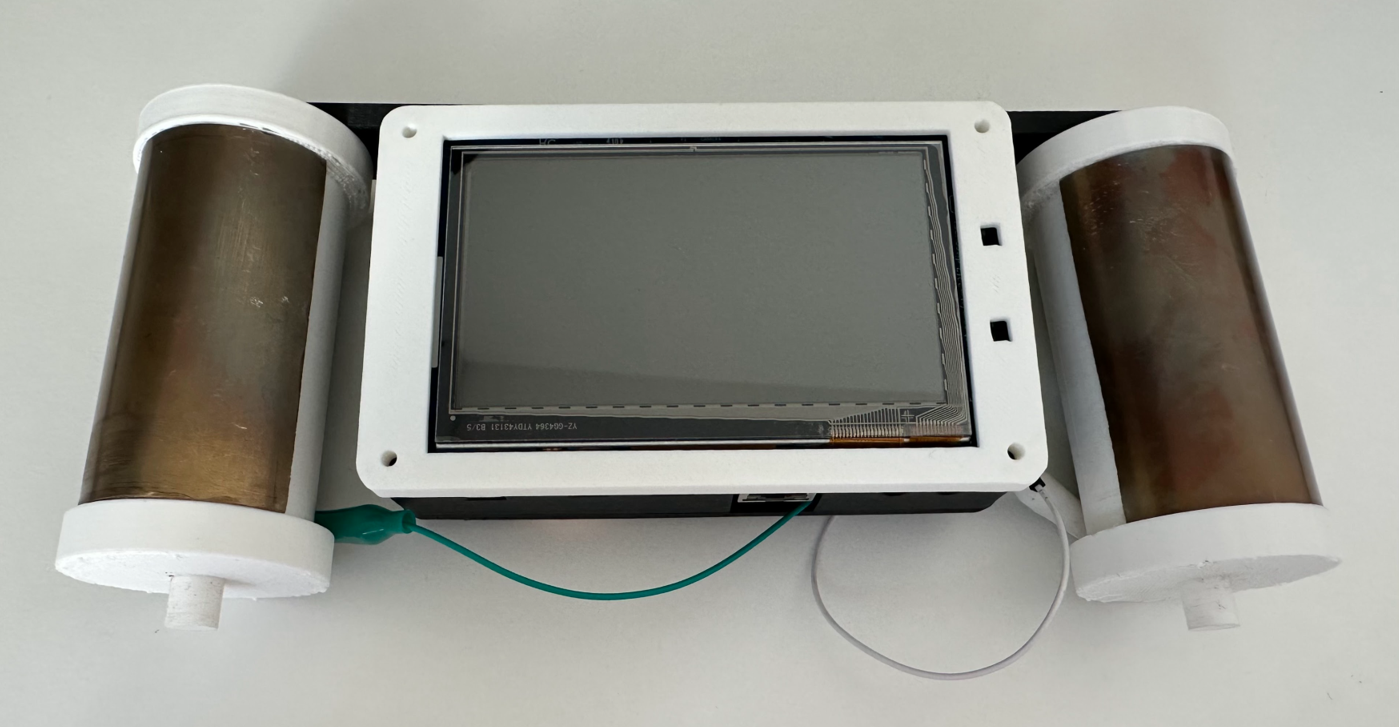
Final assembled SpinTrack device with touchscreen UI and handlebar enclosure
TouchGFX User Interface
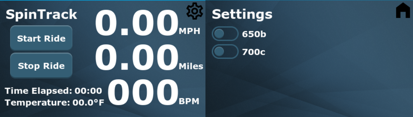
TouchGFX interface design showing real-time cycling metrics and controls
The TouchGFX-based interface displays all cycling metrics in a clean, easy-to-read layout optimized for outdoor visibility. The main screen shows speed and distance as primary metrics in large fonts, with secondary data (time, temperature, heart rate) arranged below. The 650b/700c wheel size toggle allows quick switching between wheel diameter settings for accurate speed calculations. The settings button (top right) provides access to configuration options. All UI elements use high-contrast colors (white text on dark background with red accents) for readability during rides. The FreeRTOS UI task refreshes the display at a consistent framerate while other tasks handle sensor polling in parallel.
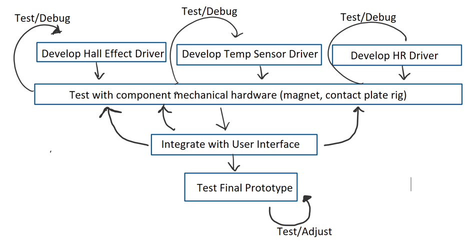
High-Level System Architecture
- STM32F746 microcontroller with ARM Cortex-M7 core (216 MHz) for real-time processing and TouchGFX graphics
- FreeRTOS task scheduler with four concurrent tasks: Hall-Effect Driver, Temperature Sensor Driver, IIR Driver, User Interface
- Test/Debug framework providing component-level verification before system integration
- Hall-effect sensor connects via ADC peripheral for wheel rotation detection and speed calculation
- Temperature sensor interfaces through I2C bus for ambient and body temperature readings
- AD8232 heart-rate monitor with custom contact plates for ECG acquisition
- TouchGFX graphics pipeline renders UI at consistent framerate while sensors poll independently
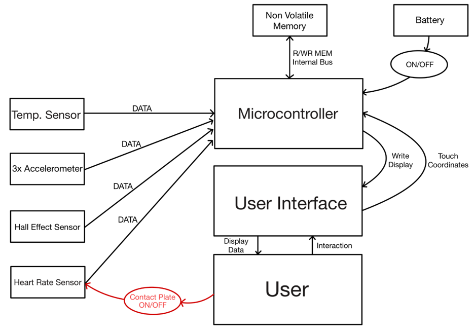
System architecture showing FreeRTOS task structure and sensor integration
Custom Contact Plate Design
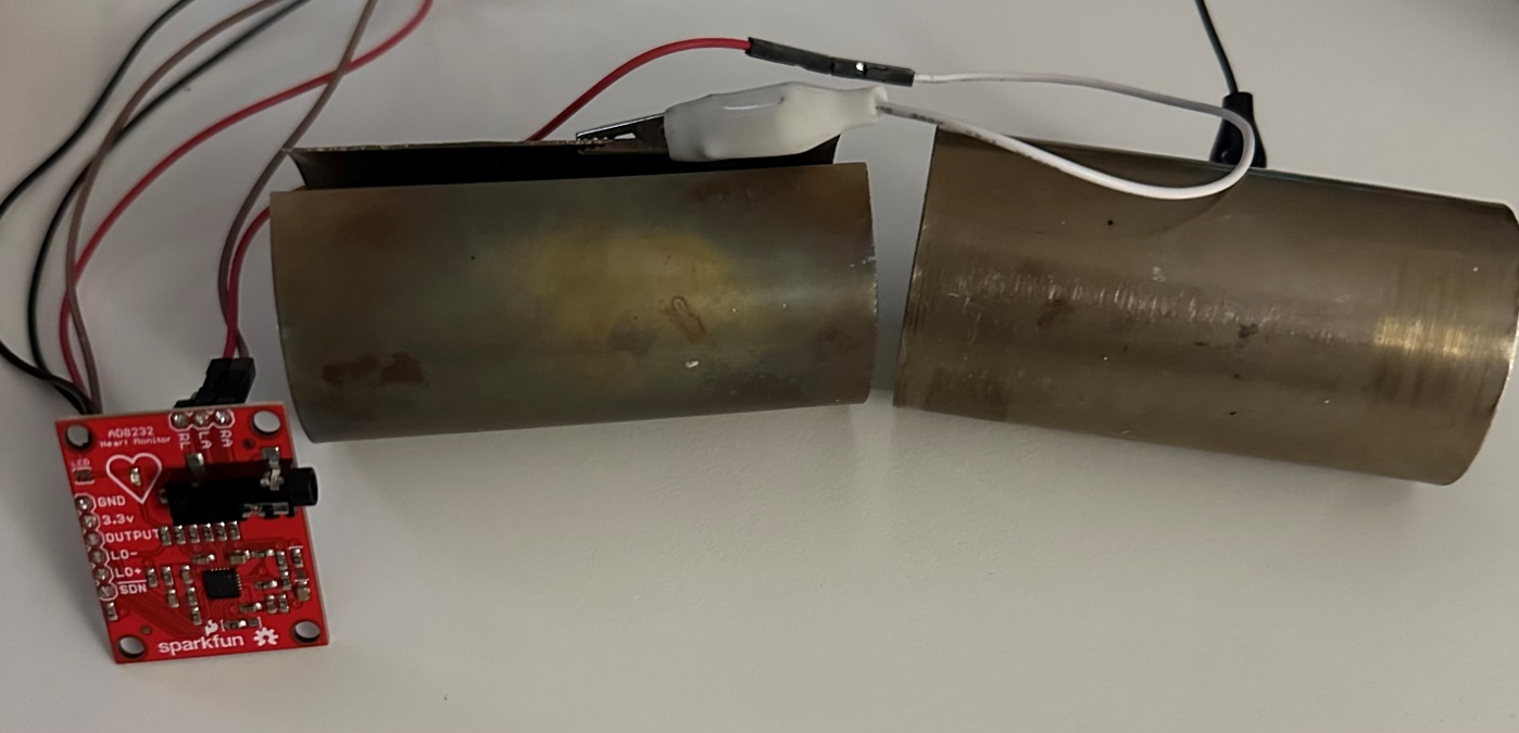
Custom handlebar contact plates for AD8232 heart-rate sensing
The heart-rate monitoring system uses custom-designed copper contact plates integrated into handlebar grips. These plates connect to the AD8232 analog front-end (ECG sensor) for continuous heart-rate measurement during rides. The contact plates are positioned for natural hand placement, ensuring consistent skin contact without requiring special grip adjustment. A magnetic mounting system allows easy installation and removal. The mechanical design includes strain relief for wiring and protective coating to prevent corrosion from sweat and weather exposure. This custom hardware solution eliminates the need for chest strap monitors while maintaining accurate BPM tracking.
Hardware System Construction
The hardware assembly process integrates multiple subsystems: (1) STM32F746 Discovery board mounted in custom board cage, (2) AD8232 heart-rate module with contact plate wiring, (3) Hall-effect sensor positioned for magnet detection, (4) Temperature sensor I2C connection, (5) Battery pack with voltage regulation, (6) Touchscreen display connector. The modular board cage design provides secure mounting while allowing access for debugging and firmware updates. Cable management ensures wires remain organized and protected during use. The construction emphasizes accessibility for testing while maintaining structural integrity for handlebar mounting.
Hardware assembly showing STM32 board, sensors, and wiring integration
Enclosure Design & 3D Models
The final enclosure consists of three custom 3D-printed components: (1) Main housing with touchscreen cutout and mounting bracket, (2) Handle mount for secure handlebar attachment, (3) Board cage for STM32 and sensor mounting. The design prioritizes weather resistance, vibration dampening, and easy maintenance access. The handle mount features adjustable clamp mechanism compatible with standard handlebar diameters (22-32mm). Ventilation slots prevent heat buildup while maintaining splash resistance. The modular cage design allows component replacement without disturbing other subsystems. All models were created in CAD software and printed in ABS plastic for durability.
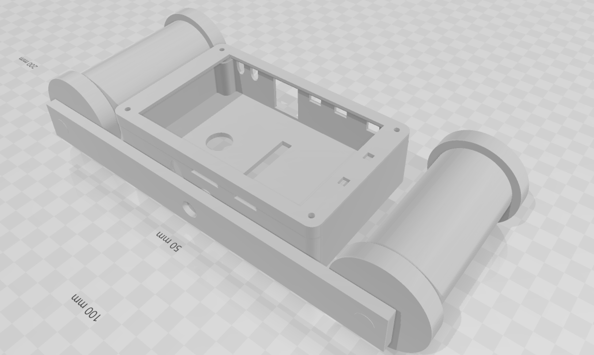
3D CAD models showing enclosure, handle mount, and board cage components
Software Architecture & FreeRTOS
- Applied agile, sprint-based development methodology for iterative feature implementation
- FreeRTOS task scheduler ensures deterministic timing for sensor polling and UI refresh
- Hall-Effect Driver task: ADC peripheral reads magnetic field, calculates RPM, converts to MPH based on wheel circumference
- Temperature Sensor Driver: I2C communication with periodic polling and data buffering
- IIR Driver: Digital filtering for heart-rate signal processing and BPM calculation
- User Interface task: TouchGFX graphics pipeline renders live data at consistent frame rate
- Test/Debug framework for component-level verification and system integration testing
Implementation Challenges & Solutions
Key technical challenges included: (1) Contact plate reliability - solved through optimized plate geometry and conductive coating, (2) Hall-effect noise filtering - addressed with ADC averaging and threshold tuning, (3) FreeRTOS task timing - resolved through priority adjustment and watchdog timers, (4) TouchGFX performance - optimized by reducing refresh rate and simplifying graphics layers, (5) Power consumption - minimized through low-power modes and duty cycling non-critical sensors. The iterative development process allowed early identification of these issues and systematic solution implementation.
Results & Takeaways
Successfully integrated multiple hardware, software, and mechanical subsystems into a functional real-time embedded product. The system demonstrates responsive performance with smooth UI updates and accurate sensor readings. Early system architecture and requirements definition proved critical for managing complexity across sensor integration, UI design, and task scheduling. Real-time constraints significantly impacted sensor selection, UI responsiveness, and FreeRTOS task prioritization. The modular design enables future expansion with GPS, wireless connectivity, and additional physiological sensors. The project showcases the importance of balancing hardware capabilities, software architecture, and user experience in embedded system design.